3.5.1 Current electricity
3.5.1.1 Basics of electricity
Charge
- Measured in coulomb (C)
- Charge of 1 electron = \(-1.60 \times 10^{-19} \text{ C}\)
- Scalar quantity
Electric current (I)
- The rate of flow of charge
- \(I = \frac{\Delta Q}{\Delta t}\)
Potential difference (V)
- The energy transferred per unit charge between two points in a circuit
- When a charge of 1 C passes through a p.d. of 1 V, it does 1 J of work
- \(V = \frac{W}{Q}\)
Resistance (R)
- A measure of how difficult it is for charge carriers to pass through a component
- \(R = \frac{V}{I}\)
Capacity
- A measure of the total amount of charge which the battery can push around a circuit
- Commonly measured in ampere-hours (A h)
- 1 Ah = a current of 1 A can flow for 1 hour = 3600 C
Types of charge carriers
- Insulator
- Each electron is attached to an atom and cannot move away from the atom
- Metallic conductor
- Most electrons are attached to metal ions but some are delocalised
- Delocalised electrons can carry charge through the metal
- When a voltage is applied across the metal these conduction electrons are attracted towards the positive terminal of the metal
- Semiconductor
- Number of charge carriers increase with an increase of temperature (electrons break free from the atoms of the semiconductor)
- Resistance fall as temperature rise
3.5.1.2 Current-voltage characteristics
Ohm's law
- The current through a conductor is directly proportional to the potential difference across the conductor provided that temperature and other physical conditions remain constant
- \(V = IR\)
- Not the definition of voltage
Types of different conductors
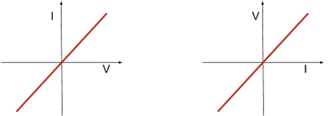
- Ohmic conductor
- Follows Ohm’s law
- Constant resistance as long as temperature and other physical conditions remain constant
- Current-voltage graph will look like a straight line through the origin
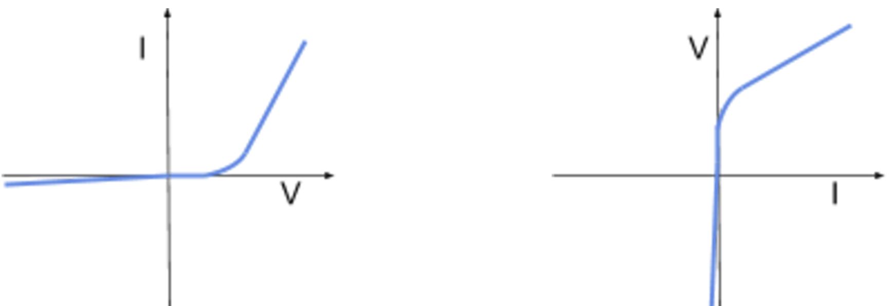
- Semiconductor diode
- Only lets current flow in one direction, converts AC to DC
- Forward biased: allow current to flow easily past the threshold voltage (smallest voltage needed to allow current to flow)
- Reverse biased: the resistance of the diode is extremely high so that only a very small current can flow
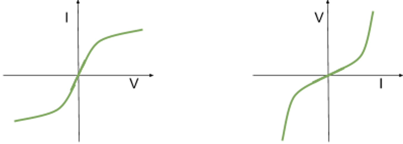
- Non-ohmic conductors e.g. filament lamp
- Ohm's law obeyed initially (a straight line initially)
- Does not have a constant resistance
- As voltage increases current increases
- More electrons flow through the wire per second
- Current heats filament
- Higher rate of collisions between ions in the lattice structure and electrons
- Conducting electrons slow down more and lose more kinetic energy so current falls and resistance increases
- Rate of increase of current is less than if resistance was constant
- As current or voltage increases resistance increases so the gradient is not constant
- Negative voltage and current produces the same effect
Assumptions
- Assume ammeters and voltmeters are ideal unless otherwise stated
- Ammeters can be assumed to have zero resistance
- Voltmeters can be assumed to have infinite resistance
3.5.1.3 Resistivity
Resistivity (\(\rho\))
- Resistance per unit length \(\times\) area of cross section
- \(\rho = \frac{RA}{L}\) or \(R = \frac{\rho L}{A}\)
- Unit = \(\Omega \text{m}\)
Effect of temperature on the resistance of metal conductors
- When the temperature of a metal conductor increases its resistance will increase
- Metal ions gain KE from heating and vibrate more so they take up more space
- More collisions between electrons and metal ions per second so they slow down more
- Current falls so resistance increases
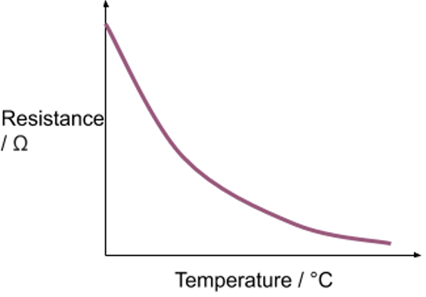
Effect of temperature on the resistance of thermistors
- When the temperature of a thermistor increases, its resistance will decrease
- Increasing the temperature of a thermistor causes electrons to be emitted from atoms = more charge carriers = current increase
Application of thermistors
- Temperature sensors
- Trigger an event to occur once the temperature drops below or reaches a certain value
- e.g. turn on the heating once room temperature drops below a specific value
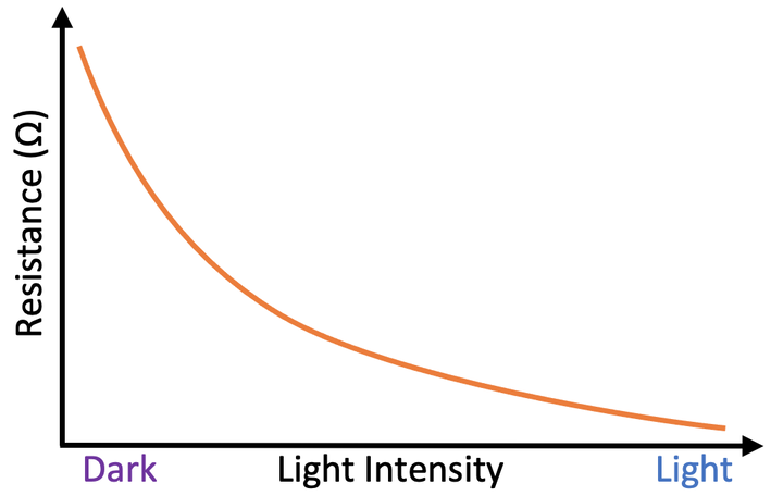
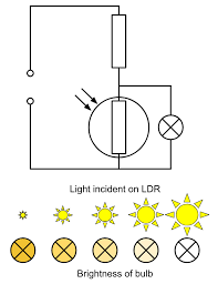
LDR
- Resistance decreases as light intensity increases
- Used to trigger certain events
Superconductivity
- A property of certain materials which have zero resistivity at and below a critical temperature (\(T_{c}\)) which depends on the material
- Resistivity decreases as temperature decreases
- Zero resistivity = zero resistance
- Critical temperature normally extremely low (close to 0 K)
Applications of superconductors
- Power cables
- Reduce energy loss due to heating to zero during transmission
- Production of strong magnetic fields
- Do not require a constant power source
- Used in maglev trains / certain medical applications
Resistance of a wire
- Normally assumed to be 0 so no PD is lost between 2 points on a wire with no resistors between them
- The assumption can break down if the current is high / resistance in the rest of the circuit is low
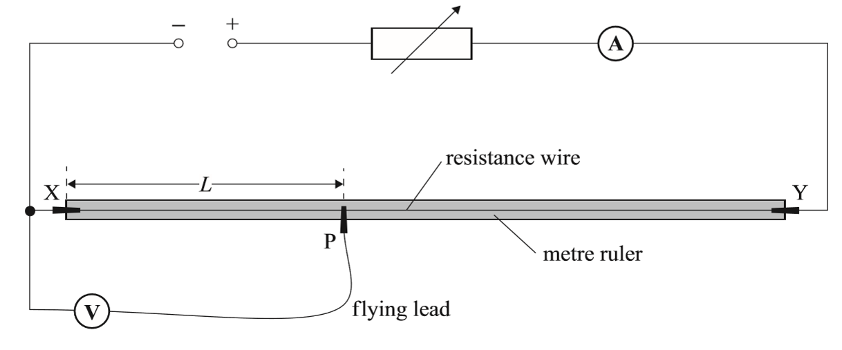
Required practical 5 - determining wire resistivity
Method
- Set up the circuit as shown
- Connect the flying lead to the wire so that 0.10 m of the wire has its resistance measured
- Switch on the power supply and adjust the voltage of it so that the current in the circuit is 0.50 A
- Turn off the power supply between readings so the wire does not heat up and increase in resistance
- Measure and record the length and voltage across the wire by taking reading on the voltmeter
- Move the flying lead to increase the length by 0.10 m and repeat the measuring process for lengths up to 1.00 m
- Repeat the experiment twice for each reading and calculate an average voltage at each length
- Calculate resistance at each length by \(R = \frac{V}{I}\)
- Plot a graph of resistance against length
- Resistivity = gradient \(\times\) cross sectional area (gradient = \(\frac{\rho}{A}\))
Errors
- Random Errors
- The current flowing through the wire will cause its temperature to increase and increase its resistance and resistivity
- Only allow small currents to flow through the wire so the temperature is kept constant and low
- The power supply should be switched off between readings so its temperature doesn't change its resistance
- Make at least 5-10 measurements of the diameter of the wire with the micrometer screw gauge and calculate an average diameter to reduce random errors in the reading
- The wire should be free from kinks and held straight so the measurement of the length is as accurate as possible.
- The current flowing through the wire will cause its temperature to increase and increase its resistance and resistivity
- Systematic errors
- Zero error when measuring wire length
Safety Considerations
- When there is a high current, and a thin wire, the wire will become very hot
- Make sure never to touch the wire directly when the circuit is switched on
- Switch off the power supply right away if you smell burning
- Make sure there are no liquids close to the equipment, as this could damage the electrical equipment
3.5.1.4 Circuits
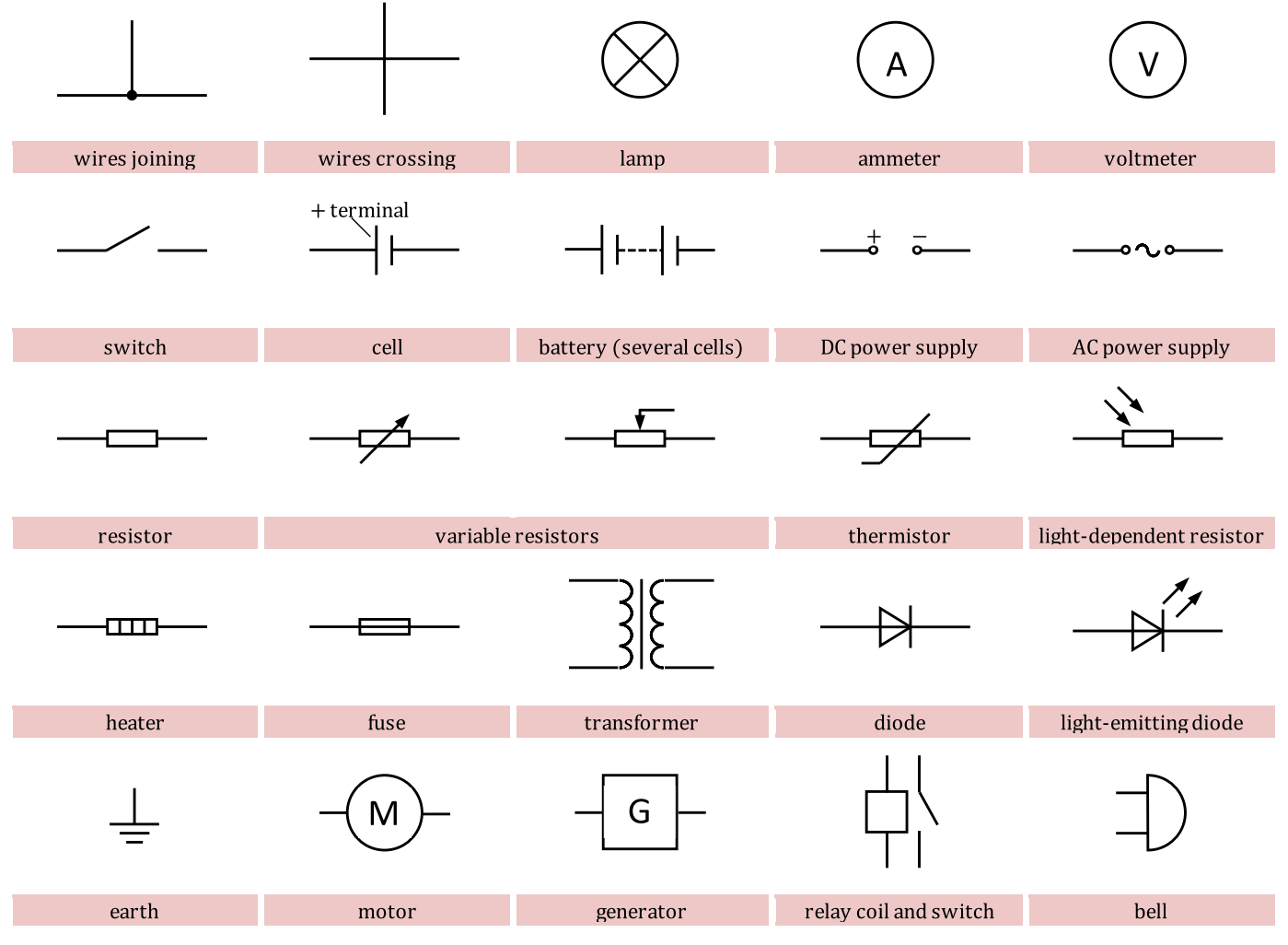
Circuit symbols
Series circuit properties
- The current is the same at all points
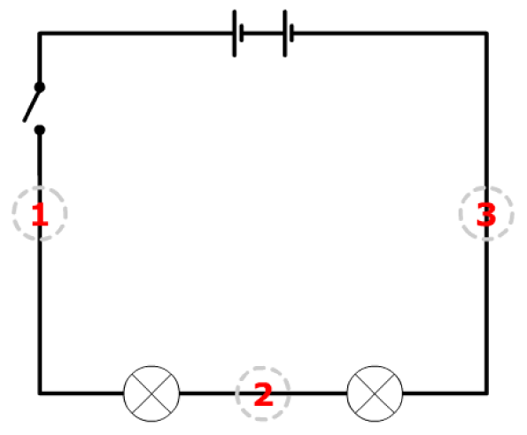
- ① = ② = ③
- The sum of potential differences across the components is equal to the total EMF of the power supply
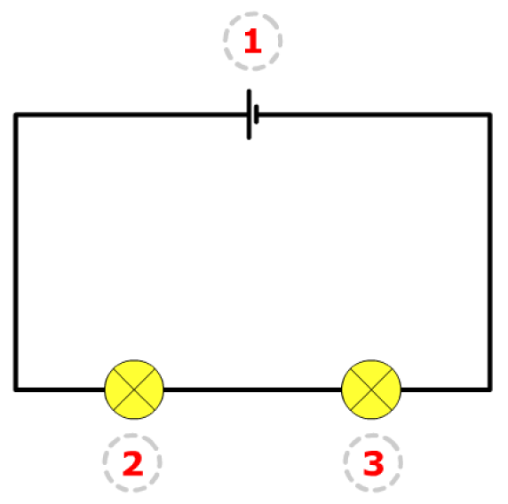
- ① = ② + ③
Parallel circuit properties
- The current splits up
- Some of it going one way and the rest going the other
- Total current in the circuit = sum of the currents in the branches
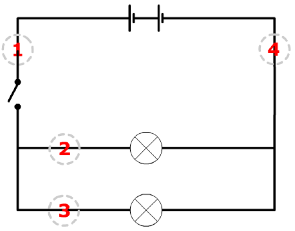
- ① = ② + ③ = ④
- Total voltage of a parallel circuit has the same value as the voltage across each branch
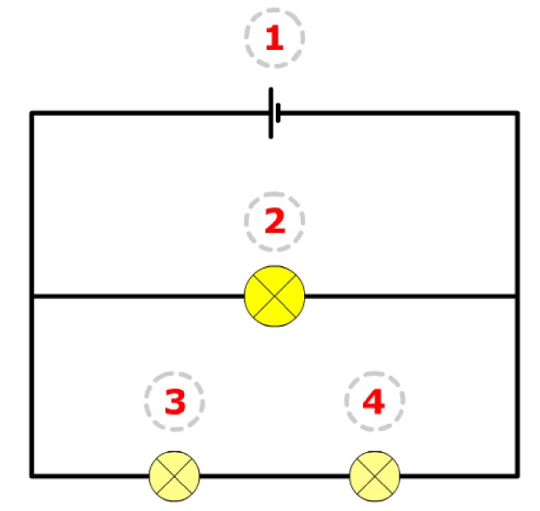
- ① = ② = ③ + ④
Total voltage of cells
- Cells joined in series
- \(V_{T} = V_{1} + V_{2} + V_{3} + \ldots\)
- Identical cells joined in parallel
- Total voltage = voltage of one cell as current is split equally between branches so overall pd is the same as if the total current was flowing through a single cell
- \(V_{T} = V_{1} = V_{2} = V_{3} = \ldots = \epsilon - \frac{Ir}{n} = \text{emf} - \frac{\text{total current of the circuit} \times \text{internal resistance of each cell}}{\text{number of cells}}\)
- Total internal resistance = calculated in the same way as other parallel circuits
- Act like one cell but with reduced internal resistance
Advantages of cells joined in parallel
- Reduce the combined internal resistance of the cells - reduce lost volts
- Less power drawn from each cell so it lasts longer
Total resistance calculation
- In series
- \(R_{T} = R_{1} + R_{2} + R_{3} + \ldots + R_{n}\)
- In parallel
- \(\frac{1}{R_{T}} = \frac{1}{R_{1}} + \frac{1}{R_{2}} + \frac{1}{R_{3}} + \ldots + \frac{1}{R_{n}}\)
Power (\(P\)) and energy (\(E\))
- \(P = IV = \frac{V^{2}}{R} = I^{2}R\)
- \(E = Pt = IVt\)
Kirchhoff's laws
- In DC circuits
- Kirchhoff's first law (conservation of charge)
- The total current flowing into a junction is equal to the current flowing out of that junction
- No charge is lost at any point in the circuit
- Kirchhoff's second law (conservation of energy)
- The sum of all the voltages in a series circuit is equal to the battery voltage
- No energy is lost at any point in a circuit
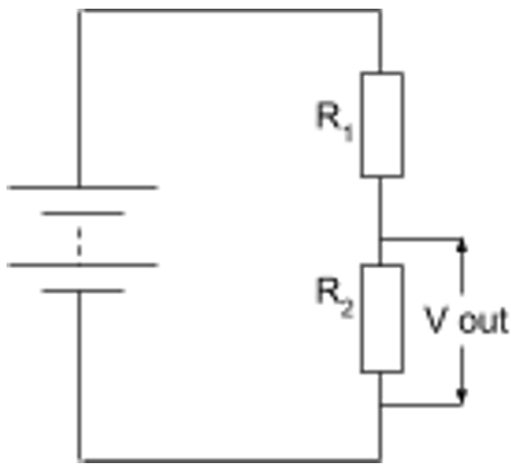
3.5.1.5 Potential divider
Potential divider
- Circuits which produce an output voltage as a fraction of its input voltage
- Has several resistors in series connected across a voltage source
- Used to supply constant or variable potential difference from a power supply
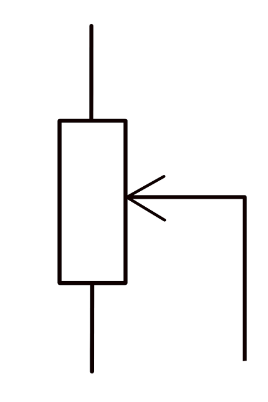
Using variable resistors
- Potential divider supply a variable pd
- Use variable resistor as one of the resistor in series
- Vary the resistance across = vary pd output
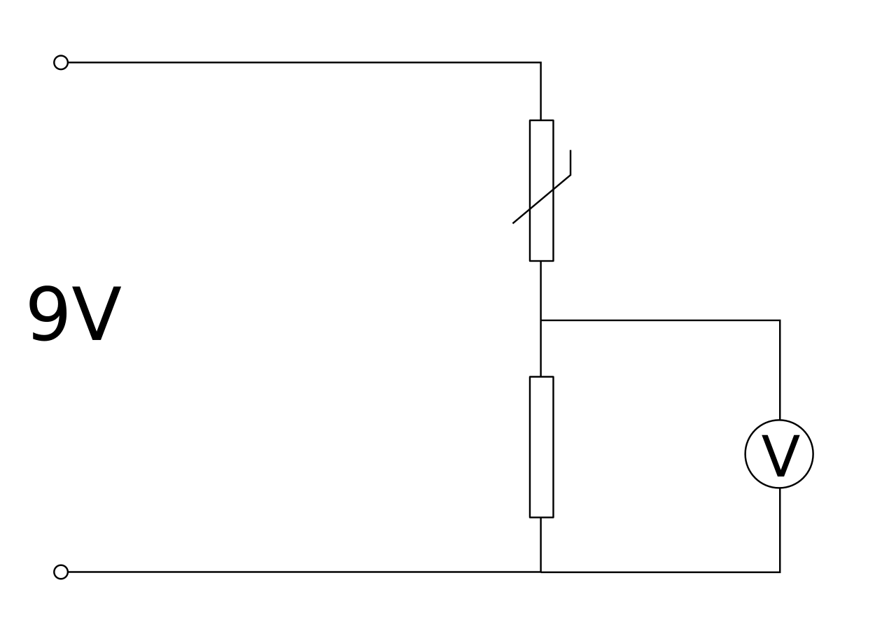
Using thermistor / LDR
- Resistance decreases as temperature / light intensity increases
- Used to trigger certain events
Change in voltage across one resistor
- Resistance stayed constant
- Current increase / decrease \(\rightarrow\) voltage across changes
- Resistance changed
- The resistor has increased / decreased share of total resistance
- New current is the same in both resistors
- The resistor gets a larger / smaller share of the EMF
3.5.1.6 Electromotive force and internal resistance
Internal resistance of batteries
- The resistance of the materials within the battery
- Caused by electrons colliding with atoms inside the battery so some energy is lost before electrons leave the battery
- Represented as a small resistor inside the battery
Terminal pd (\(V\))
- Pd across the resistor(s)
- \(V = \epsilon - Ir\)
Lost volts (\(v\))
- Pd across the internal resistor in the battery
- = energy wasted by the cell per coulomb of charge
Electromotive force
- The energy converted (from chemical) to electrical energy by a cell for per coulomb of charge that passes through it
- Can be measured by measuring the voltage across a cell using a voltmeter when there is no current running through the cell
- \(\epsilon = \frac{E}{Q} = \frac{\text{electrical energy transferred}}{\text{charge}}\)
- \(\epsilon = V + v = I(R + r) = \text{current} \times (\text{load resistance} + \text{internal resistance})\)
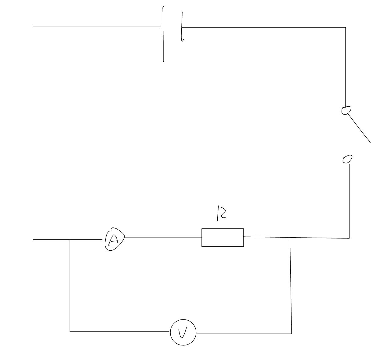
Required practical 6 - finding the EMF and internal resistance of a cell
Method
- Set up the circuit as shown above with 2 (1.5V) cells connected in series
- Connect a voltmeter across the resistor to measure the load voltage
- Close the switch so that the current flows in the circuit
- Record the ammeter and voltmeter readings
- Open the switch to cut off the current and prevent heating in the circuit
- Replace the resistor with a different resistor with a different resistance and repeat the measuring process
- Use at least 5 different resistors with different resistances
- Repeat the experiment 2 more times for each resistor and calculate the mean current and voltage
- Plot a graph of load voltage against current
- EMF of the cell is the y-intercept of the graph while the internal resistance of the cell is the magnitude of the gradient of the graph
Safety
- Another resistor can be included in series with the other to avoid high currents which could be dangerous and make the wires get hot
Improvements / controls
- Only close the switch for as long as it takes to read off each pair of readings
- Prevent the internal resistance of the battery or cell from changing during the experiment due to heating
- Use fairly new batteries/cells
- The emf and internal resistance of run down batteries can vary during the experiment