3.3.2 Refraction, diffraction and interference
3.3.2.1 Interference
Coherence
- Waves with a constant phase difference and the same frequency and wavelength
Monochromatic
- Light waves with a single wavelength only
Lasers
- Coherent and monochromatic
- Usually used as sources of light in diffraction experiments as they form clear interference patterns
Path difference
- The difference in the distance travelled by two waves from their sources to where they meet
Interference of monochromatic light
- Path difference = \(n\lambda\) \(\rightarrow\) constructive interference, gives maximum intensity / reinforcement
- Path difference = \((n + \frac{1}{2}) \lambda\) \(\rightarrow\) destructive interference, gives 0 intensity / cancellation
Interference of longitudinal waves (sound waves)
- Constructive interference / reinforcement
- Compression + compression / rarefaction + rarefaction \(\rightarrow\) greater volume
- Destructive interference / cancellation
- Compression + rarefaction \(\rightarrow\) 0 volume, used for noise cancellation
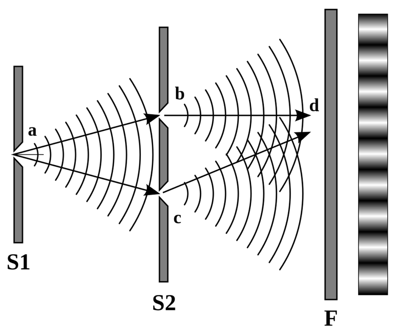
Young’s double slit experiment
- Condition for light source
- Monochromatic light source \(\rightarrow\) use colour filter
- Coherent \(\rightarrow\) single silt between light source and double silt
- Both slits will be illuminated from the same source so they receive light of the same wavelength
- Paths to both slits are of constant length giving constant phase difference (normally in phase)
- Laser is both monochromatic + coherent so no colour filter / single slit needed
- Procedure
- Shine a coherent light source through 2 slits about the same size as the wavelength of laser light so the light diffracts / use 2 coherent sources
- Each slit acts as a coherent point source making a pattern of light and dark fringes
- Light fringes are formed where the light from both slits meet in phase and interferes constructively (path difference = \(n\lambda\))
- Dark fringes are formed where the light from both slits meets completely out of phase and interferes destructively (path difference = \((n + \frac{1}{2}) \lambda\))
(Bright) Fringe spacing
- \(w = \frac{\lambda D}{s} = \frac{\text{wavelength} \times \text{distance between slit and screen}}{\text{slit spacing}}\)
Fringe spacing proof
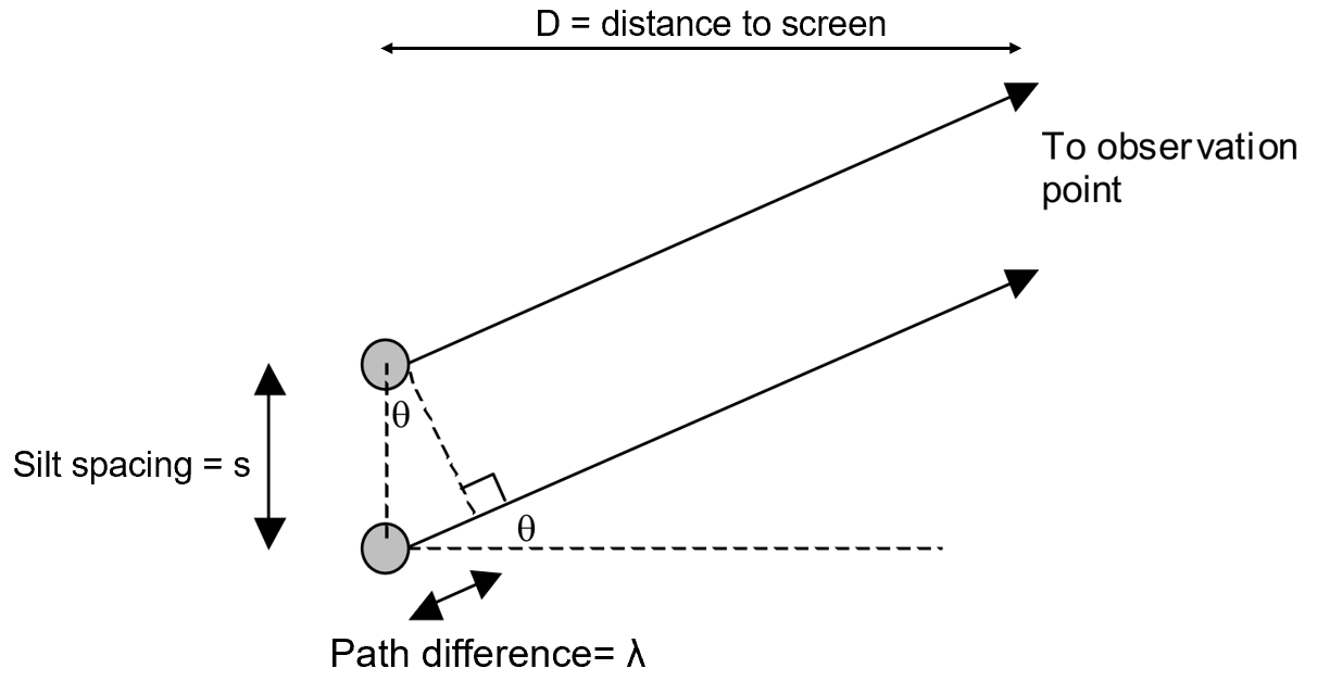
- \(\sin \theta = \frac{\lambda}{s}\)
- \(\tan \theta = \frac{w}{D}\)
- When \(\theta\) is small: \(\sin \theta \approx \tan \theta \approx \theta\) so \(\frac{\lambda}{s} = \frac{w}{D}\)
- Hence \(w = \frac{\lambda D}{s}\)
Significance of Young's double slit experiment
- Proved the wave nature of light since diffraction and interference are wave properties
- Proved that EM radiation must act as a wave
- Disproved the theories that light is formed of tiny particles
- Knowledge and understanding of any scientific concept changes over time in accordance to the experimental evidence gathered by the scientific community
Interference pattern with white light
- Wider maxima
- Less intense diffraction pattern with a central white fringe (all colours are present)
- Alternating bright fringes which are spectra, violet is the closest to the central maximum and red is the furthest
Safety precautions with lasers
- Do not look directly at a laser beam even when it is reflected
- Wear laser safety goggles
- Don’t shine the laser at reflective surfaces
- Display a warning sign
- Never shine the laser at a person
Required practical 2
Determining slit separation for double slit
- Illuminate a double slit with a red laser of known wavelength, \(\lambda\)
- Project the interference pattern onto a white screen a distance, \(D\), away from the slits
- Measure \(D\) with a tape measure
- The fringe spacing, \(w\), can be measured by measuring across several visible fringes
- Measure \(w\) using a meter rule
- Find the mean fringe spacing
- Use the double slit formula, \(w = \frac{\lambda D}{s}\) and the measurements to determine the slit separation, \(s\).
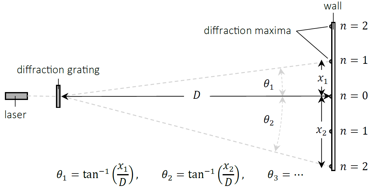
Finding average grating spacing
- Illuminate a diffraction grating with a known grating spacing with a red laser of known wavelength, \(\lambda\)
- Project the diffraction pattern onto a white screen at a distance \(D\) away from the grating.
- Measure \(D\) with a tape measure
- Measure the angles of diffraction, \(\theta_{n}\) for multiple diffraction maxima
- Measure distance from centre + use trigonometry
- Plot a graph of \(\sin \theta_{n}\) against \(n\)
- \(\text{gradient} = \frac{\lambda}{d}\)
- Use the gradient to determine the average grating spacing \(d\) and hence the average number of lines per mm, \(\frac{1}{d}\)
Finding wavelength of light
- Use a diffraction grating with a known average grating spacing and use the gradient to find the wavelength instead, otherwise same as above
3.3.2.2 Diffraction
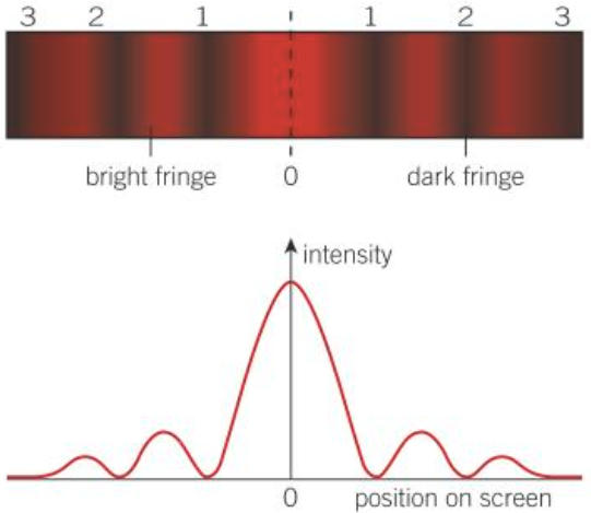
Single silt diffraction with monochromatic light
- Central maximum with highest intensity
- Decreasing intensity fringes on both sides, equally spaced
- Central fringe is twice the width of other fringes
Single silt diffraction with white (non-monochromatic) light
- White central maximum
- Distinct fringes shown with subsidiary maxima
- Fringes on both sides show as spectrums
- Red furthest, violet closest to the centre in subsidiary maxima
Effect of using narrower slit / longer wavelength
- Waves are more diffracted
- Wider spacing
- Lower intensity of fringes as the energy is spread over a larger area
Fringe spacing for single slit diffraction
- \(w = \frac{\lambda \times \text{distance from slit to screen}}{\text{slit width}} = \frac{\lambda D}{a}\)
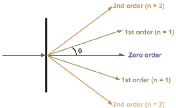
Diffraction grating explanation
- A slide containing many equally spaced slits very close together
- Light passing through each slit is diffracted
- Light from different slits superpose
- When the path difference between adjacent slits is a whole number of wavelengths the light waves arrive in phase and constructive interference occurs
- \(\text{Distances from the centre where maxima occur} = d \sin \theta = n\lambda\) (\(d\) = distance between slits)
- Angle of diffraction between each transmitted beam and the central beam increases if light of a longer wavelength or a grating with closer slits is used
Comparison to double slit
- Much sharper and brighter image when monochromatic light is passed through
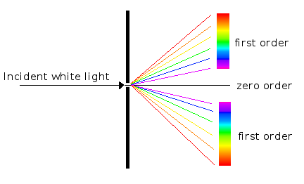
White light incident
- Spectrum is seen when white light is used
- Different colours of light have different maxima positions
- Line absorption spectra and line emission spectra can determine the elements in a substance (see photoelectric effect)
Maximum number of orders visible
- Use \(\sin \theta \le 1\)
- \(n_{max} = \lfloor \frac{d}{\lambda} \rfloor\)
Measuring wavelength of light
- Diffraction patterns are measured using a spectrometer
- Angles measured accurate to 1 arc minute (\(\frac{1}{60}^\circ\))
- It can be used to study light from any source and measure wavelengths very accurately
- Angle measured using a known wavelength \(\rightarrow\) grating spacing calculated
- Grating can then be used to measure the wavelength of any light
Applications of diffraction grating
- Diffraction gratings can be used to observe and measure spectral lines
- Line emission spectra can be used to identify elements in the vapour gas of the vapour lamp (similar to line absorption spectra)
3.3.2.3 Refraction at a plane surface
Refraction
- Change of direction and wavelength when a wave crosses a boundary and its speed changes
Refractive index of a substance
- \(n = \frac{c}{c_{s}} = \frac{\sin i}{\sin r}\)
- Refractive index of air \(\approx 1\)
- Higher refractive index = light travels slower in the substance
Refractive index of different colours
- Longer wavelength = smaller refractive index = travels faster
- Red has the smallest refractive index as it has the longest wavelength
- Violet has the largest refractive index as it has the shortest wavelength
Snell's law
- \(n_{1} \sin \theta_{1} = n_{2} \sin \theta_{2}\)
Total internal reflection (TIR)
- For ray going from more dense to less dense substance & the angle of incidence exceeds the critical angle
- No refracted light wave since the angle of refraction > 90° so all the light is reflected
Critical angle
- The angle of incidence at which the angle of refraction is 90°
- \(\sin \theta_{c} = \frac{n_{2}}{n_{1}} \quad (n_{2} < n_{1})\)
Pulse broadening
- The length of a pulse is widened so it may overlap with the next pulse
- Distorts the information in the final pulse
Pulse absorption
- Energy is absorbed by the fibre
- Amplitude is reduced so information can be lost
Solution to pulse absorption
- Use more transparent core
- Use pulse repeaters to regenerate the pulse before significant pulse broadening has taken place
Material / spectral dispersion
- Happens if white light is used instead of monochromatic light
- Different wavelengths have different speeds due to different refractive indices within the core
- Red light has the longest wavelength \(\rightarrow\) lowest refractive index, fastest
- Violet light has the shortest wavelength \(\rightarrow\) highest refractive index, slowest
- Causes pulse broadening
Solution to material dispersion
- Use monochromatic light
- Use of shorter repeaters so that the pulse is reformed before significant pulse broadening has taken place
Modal / multipath dispersion
- Light waves entered at different angles of incidence so they are spread out
- They travel different distances as they take different paths and arrive at the other end at different times
- Causes pulse broadening
Solution to modal dispersion
- Use monomode fibre / narrower core
- Use a cladding with its refractive index as close to the core as possible (larger critical angle \(\rightarrow\) less TIR)
Optical fibre structure
- Core
- The transmission medium for EM waves to progress
- Cladding
- Protects the outer surface of the core from scratching which could lead to light leaving the core
- Ensure that no light leaves the core
- RI of cladding < RI of core
- Maintains quality/reduces pulse broadening
- Prevent crossover of signal to other fibres
Refractive index of cladding
- Similar RI between cladding and core
- Larger critical angle \(\rightarrow\) less TIR \(\rightarrow\) less modal dispersion
- RI of cladding much smaller than core
- Smaller critical angle (greater acceptance angle) \(\rightarrow\) less light escape \(\rightarrow\) more light collected
Types of optical fibre
- Step index fibre
- The refractive index of each component increases moving from the outside to the centre of the fibre
- The refractive index within each component is uniform
- Graded index fibre
- Has a core that has a gradually increasing refractive index from outside to centre
Applications of optical fibres
- Endoscopes
- Transmission of data for communications
Producing coherent image
- An incoherent bundle cannot be used to form an image because the ends of the individual fibres are arranged randomly so the image is incorrect
- In a coherent bundle, the fibres have the same spatial position at each end of the bundle.
- The light emitted from the end of the bundle is an exact copy of the incident light and a single image can be reproduced and analysed
- Coherent bundles are expensive to manufacture so incoherent bundles are used for illumination
Advantages of optical fibres
- Less loss of strength
- No interference
- Greater bandwidth for more information per second
- Increased security